


Coil Bracket Replacement for TJ-LJ-XJ-ZJ front axle
SKU : TJ3017
Regular price
$307.99
$261.79
Coil Bracket Replacement for TJ-LJ-XJ-ZJ front axle

- Apex design provides more rigidity than a flat top truss design. Patent Pending
- CNC precision laser cut
- Dimpled holes provide light weight and rigidity
- CNC precision bending ensures perfect fitment
- Hassle-free installation: Reinforced truss – simply drop it in place and start welding
- 3D models from Dana Corp and vehicle OEM for perfect fit and clearance.
- 70% less welding needed than previous designs for less warping, faster turnaround, lower costs
- Contours to both the cast steel differential and FAD (front Axle disconnect)
- Worry-free wheeling for multiple tire sizes on stock axles
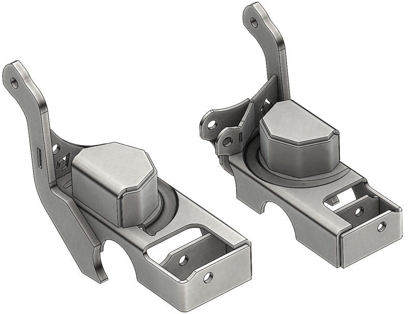
Coil Spring Axle Bracket – Front & Shock Axle Bracket Elevate your off-roading experience with Artec Industries’ Front Axle Coil Bracket Replacement. Replace your coil buckets and shock mounts with our heavy-duty bracket for unmatched durability. Our 3/16” thick bracket includes a stamped coil correction, ensuring top performance on any terrain. Don’t compromise on equipment quality. Choose Artec Industries for the ultimate off-roading experience. Made in the USA. Optional Upgrade: Artec Industries’ Lower Control Arm Brackets offer three options – 0 degree, 10 degree, 25 degree angles – for optimal installation flexibility.
Notes : Some changes to factory positions have been altered. The Anti-sway bar bracket hole is 2.75" higher than factory hole to allow for clearance with crossover steering.
Reviews
Install Instructions

Community Discussion