


AAM 9.25 Lower Truss with Inner C Gussets
SKU : TR9251
Regular price
$309.99
$263.49
AAM 9.25 Lower Truss with Inner C Gussets

- 1/4" thick mild steel, precision CNC design
- Maintains ground clearance under differential
- Enhanced structural rigidity, better obstacle clearance
- Reinforces entire axle tube length
- Ideal for fast driving and jumping vehicles
- Includes upper Inner C gussets for total reinforcement
- 6 separate pieces for easy shipping/installation
- Made in the USA
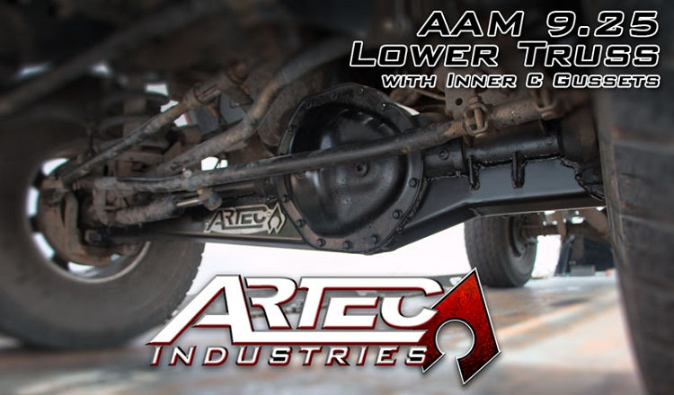
Artec Industries introduces the NEW AAM 9.25 Truss, designed to reinforce the entire front axle on Dodge 3rd Gen Rams 2500 and 3500 (2003-2012). Heavy engines on these trucks can lead to axle bending or breaking. This truss allows maximum up-travel with minimal ground clearance loss under the differential. Perfect for off-roading enthusiasts, the truss is CNC cut and formed for a great fit, requiring little-to-no grinding or modifications during installation.
Reviews
Install Instructions
Warning: This Part Requires General Mechanical Abilities If you are not confident in your abilities
Please have this product installed at a Local Off-Road Shop .
Tools Required:
Safety Glasses, Gloves, Wrench set, Socket Set, Torque
wrench, , Tie rod separator, Jack, Jack
stands(Tall and short) , Wheel chock,, Cutting tool (sawzall , cutoff
wheel, plasma cutter ect...) Welder and welding ppe.
Step 1:
Take an inventory of your parts, If you are missing any parts Please contact
Artec Industries Immediately @ (855) 278-3299
M-F 8:30am-5pm MST if it is after those hours please email us pictures
of what you received , along with product lables on the box and packing slip at
Sales@artecindustries.com
Step 2:
Place Wheel chocks at the rear wheels on the vehicle. with the vehicle on the ground break the lug
nuts on the wheels free (Do not fully loosen or remove them.) Using a jack raise up the front of the
vehicle and place tall jack stands under the frame behind the lower control arm
mounts. and a shorter set under the
axle.
Step 3:
Remove wheels from vehicle,
Remove front drive shaft from the axle ,
Remove the brake calipers and rotors (Set the rotors on a flat surface
so they do not warp), Hang the calipers
from the body with some bungee cords (Do not let the calipers hang freely from
the brake lines this can damage them.) Remove cotter pins on Tie rods, Then loosen the castle nuts. (Leave the castle nuts installed by a few threads ! ) Remove the
Steering stabilizer , Grab your Tie rod
Separator, wedge it between the knuckle and the base of the tie rod the hit on the end of the Tie rod separator
with your Big Freaking Hammer until it pops loose. Repeat this on the other
side. Remove the castle nuts and the Drag-link and tie rod should drop off the
vehicle.
Step 4:
Remove the coil spring retainers from the axle, Remove Shocks, sway bar end links, and Track
bar.
Using a jack lower slowly lower the axle to remove the coil
springs. Raise the axle back up and
place jack stands under the axle, Remove upper and lower control arms. Pull the axle out from under the vehicle for
more room to work.
Step 5:
Clean the axle tubes
and C's of any paint, rust, and debris to prep for welding.
Step 6:
Place part tr9251-3 under the Passenger Side tube between
the Lower control arm mount and the C for the knuckle and tack weld into place.
Set tr9251-1 on the axle tube between
the diff housing and control arm bracket on the passenger side and tack weld into
place. Place tr9251-2 on the driver side Axle tube between the
differential and control arm then tack weld into place. Set Tr9251-4 between lower control arm and
the C and tack into place .
Step 7:
The c gussets are the only brackets left they are a 2 peice bracket and the larger of
the 2 brackets with the bend will slip into plce from the face of the axle the loose flat bracket will jig into place
and you will weld it from the back side of the axle.
Step 8:
Weld all of the Truss Pieces together then to the the axle
tubes and housing Move around from 1 end
to the other and work your way around the axle to keep the heat down to
minimize the risk of warping the axle . After the truss is welded on the
axle Prime and paint the axle.
Step 9:
Reinstall the axle into the vehicle and torque all bolts to factory specs .
After 50
miles Check all bolts for tightness and
tighten if needed .

Community Discussion