


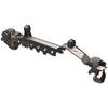
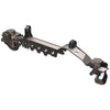
JK JL JT 1 TON - APEX Front Kingpin-Balljoint 60 Swap Kit 1985-1997
SKU : JL6533
Regular price
$516.99
$439.44
JK JL JT 1 TON - APEX Front Kingpin-Balljoint 60 Swap Kit 1985-1997

- In-house CNC laser cut from ¼" and 3/16” mild steel
- Lightweight and robust
- Hassle-free installation: Reinforced truss – simply drop it in place and start welding
- 3D models from Dana Corp and vehicle OEM for perfect fit and clearance.
- 70% less welding needed than previous designs for less warping, faster turnaround, lower costs
- Dimpled holes provide light weight and rigidity
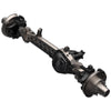
- Contours to both the cast steel differential
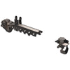
- Upper Control Arms mount to high-clearance differential bridge; fits bushing or Johnny Joint.
- The truss provides complete end-to-end rigidity by extending under coil buckets to inner C
- Coil bracket and bump stop pads are an extension of the Axle truss
- The main truss provides fixture points for all suspension brackets for easy installation
- Improved shock bracket position compared to OEM locations.
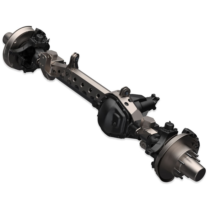
The PATENTED APEX Truss system represents the next evolution of Axle trusses from Artec Industries, combining affordability, durability, lightness, and ease of installation to provide unparalleled protection for your Axle. Its innovative peaked top design offers greater rigidity, lower weight, and no long weld seams, streamlining the installation process. The Apex swap kit features multiple enhancements, including improved weldability, less welding distortion, optimized shock bracket locations, and lower & upper control arm mounts, all suggested by our network of trusted dealers and installers. This robust truss and bracket system accommodates the factory link, spring, anti-sway bar, and shock locations while withstanding extreme wear and tear. The 3/16” thick steel truss allows easy alignment of the link mounts, saving you time and hassle during the installation.
Notes : This kit does not include any parts for ABS sensors. It is only a bracket kit. Hooking up and configuring these sensors is the responsibility of the end user.
Reviews
Install Instructions
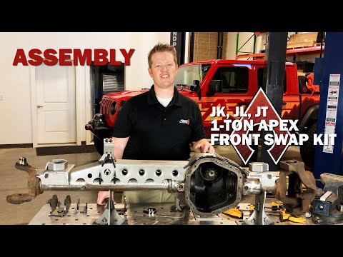
Install Videos for JL6533

Community Discussion